


Guangzhou Rongtao Medical Tech LTD.
- Annual Revenue 5,000,000-10,000,000 USD
- Employees 50~60
- Year Established 2014
- Distributor/Wholesaler, Exporter, Trading Company, Seller


Certification
See All


 Copyright 2023 ucbis.com All Rights Reserved.
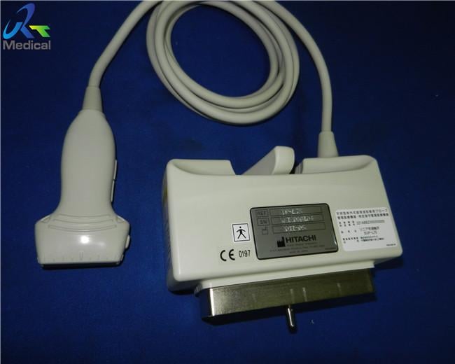
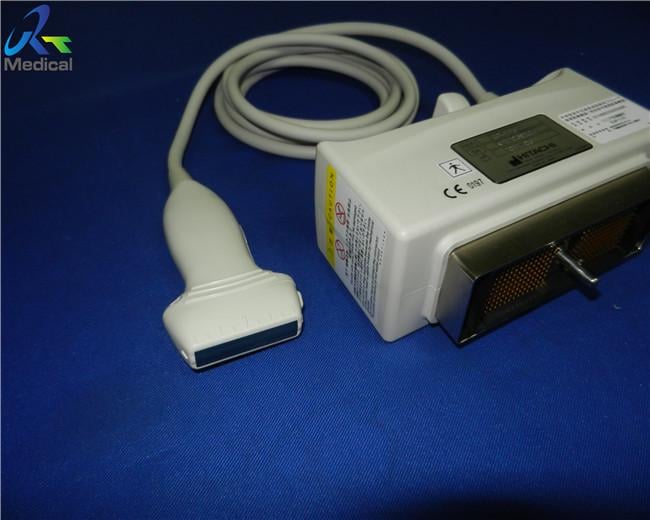
Hitachi Avius EUP-L73S 38mm Linear Ultrasound Transducer Probe
Hitachi EUP-L75 38mm Linear Ultrasound Transducer
1. Type:linear
2. Frequency: 5.0-18MHz
3. Compatible system:Hitachi Avius
4. Condition: original, in good working condition
5. With 60 days warranty
Other Hitachi probes we can offer:
| Brand | Model | Compatible System |
| Hitachi | EUP-C314G | EUB-405/525/555 |
| Hitachi | EUP-C514 | EUB-6000 |
| Hitachi | EUP-C516 | EUB-405/500/525/2000/5500/6500/8500 |
| Hitachi | EUP-C715 | H21/EUB-6500/ EUB-7500/ EUB-8500 |
| Hitachi | EUP-L33 | EUB-405/500/525/2000/5500/6500/8500 |
| Hitachi | EUP-L33ST | Eidos/EUB-525/ H20/EUB-6000 |
| Hitachi | EUP-L34T | EUB-900/5500/6500/8500 |
| Hitachi | EUP-L53 | EUB-405/500/525/2000/5500/6500/8500 |
| Hitachi | EUP-L53S | EUB-415/ Eidos/EUB-525 last version/ H20/EUB-6000/ H21/EUB-6500 |
| Hitachi | EUP-L65 | EUB-6500/ EUB-7500/ EUB-8500 |
| Hitachi | EUP-L73S | EUB-900/H19/EUB-5500/ H21/EUB-6500/ EUB-7500/EUB-8500 |
| Hitachi | EUP-L74M | EUB 6500/EUB 8500 |
| Hitachi | EUP-L75 | Avius |
| Hitachi | EUP-L54MA | EUB-405/ EUB-500/ Eidos/EUB-525/ EUB-2000/ H19/EUB-5500/ EUB-8500/ H21/EUB-6500 |
| Hitachi | EUP-V53W | EUB-405/500/525/2000/5500/6500/8500 |
| Hitachi | EUP-S50 | EUB-6500 |
| Hitachi | EUP-S50A | H19/EUB-5500/ H21/EUB-6500/ EUB-7500 |
| Hitachi | EUP-S70 | AVIUS/ PRERUS |
Various Ultrasound Systems that we served
| Hitachi-Aloka Ultrasound System |
| F31, F37, SSD-3500, SSD-3500 SV, SSD-4000, SSD-5000, ALPHA 5, ALPHA 6, ALPHA 7, ALPHA 10, PROSOUND F75, HI VISION AVIUS, HI VISION PREIRUS, EUB-5500, EUB-6500, EUB-7500, EUB-8500, Arietta 60, Arietta 70, Ascendus... |
Knowledge Point
From sound to image
The creation of an image from sound is done in three steps – producing a sound wave, receiving echoes, and interpreting those echoes.
Producing a sound wave
A sound wave is typically produced by a piezoelectric transducer encased in a plastic housing. Strong, short electrical pulses from the ultrasound machine drive the transducer at the desired frequency. The frequencies can be anywhere between 1 and 18 MHz, though frequencies up to 50–100 megahertz have been used experimentally in a technique known as biomicroscopy in special regions, such as the anterior chamber of the eye. Older technology transducers focused their beam with physical lenses. Newer technology transducers use digital antenna array techniques to enable the ultrasound machine to change the direction and depth of focus.
The sound is focused either by the shape of the transducer, a lens in front of the transducer, or a complex set of control pulses from the ultrasound scanner, in the (beamforming) technique. This focusing produces an arc-shaped sound wave from the face of the transducer. The wave travels into the body and comes into focus at a desired depth.
Materials on the face of the transducer enable the sound to be transmitted efficiently into the body (often a rubbery coating, a form of impedance matching). In addition, a water-based gel is placed between the patient's skin and the probe.
The sound wave is partially reflected from the layers between different tissues or scattered from smaller structures. Specifically, sound is reflected anywhere where there are acoustic impedance changes in the body: e.g. blood cells in blood plasma, small structures in organs, etc. Some of the reflections return to the transducer.
Receiving the echoes
The return of the sound wave to the transducer results in the same process as sending the sound wave, except in reverse. The returned sound wave vibrates the transducer and the transducer turns the vibrations into electrical pulses that travel to the ultrasonic scanner where they are processed and transformed into a digital image.
Forming the image
To make an image, the ultrasound scanner must determine two things from each received echo:
- How long it took the echo to be received from when the sound was transmitted.
- How strong the echo was.
Once the ultrasonic scanner determines these two things, it can locate which pixel in the image to light up and to what intensity.
Transforming the received signal into a digital image may be explained by using a blank spreadsheet as an analogy. First picture a long, flat transducer at the top of the sheet. Send pulses down the 'columns' of the spreadsheet (A, B, C, etc.). Listen at each column for any return echoes. When an echo is heard, note how long it took for the echo to return. The longer the wait, the deeper the row (1,2,3, etc.). The strength of the echo determines the brightness setting for that cell (white for a strong echo, black for a weak echo, and varying shades of grey for everything in between.) When all the echoes are recorded on the sheet, we have a greyscale image.
Displaying the image
Images from the ultrasound scanner are transferred and displayed using the DICOM standard. Normally, very little post processing is applied to ultrasound images.